1. What an OTDR Actually Does
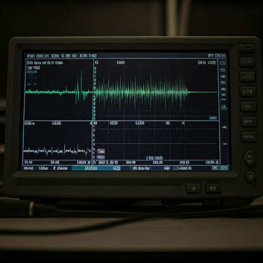
An Optical Time Domain Reflectometer sends a short pulse of laser light down a fiber and measures the return signal. Because light travels at a known speed through glass, the instrument can calculate precisely how far from the launch point any event occurs. The output is a waveform — the OTDR trace — that shows signal power on the vertical axis and distance on the horizontal axis.
An engineer who knows how to read a trace can confidently assess the fiber's physical condition, including splice losses, connector reflectance, and fault locations, thereby reinforcing trust in network reliability.
2. The Key Features on an OTDR Trace
The Launch Slope
The trace begins with a steep downward slope — the backscatter from the launch cable. A well-calibrated launch removes the near-end dead zone that would otherwise obscure the first connector or splice. The slope of the backscatter line indicates fiber quality: a steeper slope means higher attenuation for standard G. 652. D single-mode fiber, expect approximately 0.35 dB/km at 1310 nm and 0.20 dB/km at 1550 nm.
Reflective Events — Connectors
Connectors appear as spikes on the trace — the Fresnel reflection from the glass-to-air interface at a physical contact. Each spike is followed by a step down, representing the connector's insertion loss. Per IEC 61300-3-35, a polished APC connector end-face should produce a reflectance of better than -60 dB. A UPC connector should be better than -50 dB. A reflectance worse (less negative) than these thresholds indicates end-face contamination, damage, or a misaligned mating.
Non-Reflective Events — Fusion Splices
A fusion splice appears as a step down on the trace — a loss event with no reflective spike. This is the distinguishing characteristic of a good fusion splice: the glass is continuous across the joint, so there is no glass-to-air interface to produce a reflection. The step height is the splice loss. For a single-mode fusion splice performed to IEC 61300-3-4 standards, a loss below 0.1 dB is achievable; typical field splicing produces 0.02–0.05 dB per joint. If a fusion splice produces a reflective spike, it means the fusion was incomplete — there is a void or air gap at the joint. This is a defective splice regardless of the insertion loss reading.
The Noise Floor
The noise floor marks the limit where the instrument can no longer distinguish backscatter from electronic noise, directly affecting measurement reliability and focus.
The End of Fiber Reflection
The end of the fiber appears as a large reflective spike — the Fresnel reflection from the cleaved or connectorized far end. This confirms the fiber is continuous and unbroken to that point.
3. Reading Splice Loss — The Two-Point Method
To accurately measure splice loss, use the two-point method: measure the backscatter level immediately before and after the splice event, then calculate the difference. Do not use the instrument's automatic event-loss calculation — it uses an averaging algorithm that can mask real loss at closely spaced events.
For any splice producing a loss greater than 0.3 dB on a data center or telecom backbone application, investigate further. High splice loss at a single point indicates a problem with cleave quality, fusion parameters, or fiber alignment — and it will degrade coherent optics margin over time.
4. Bi-Directional Testing — Why Direction Matters
Always perform OTDR traces in both directions on critical fiber spans because bi-directional testing reveals true splice loss, ensuring accurate interpretation and focus on fiber integrity.
The true insertion loss of a splice is the average of measurements taken in both directions. A single-direction OTDR test on a fiber with multiple fiber types can significantly understate actual splice loss.
5. What a Usable OTDR Report Contains
A raw OTDR trace file is not a deliverable. A usable OTDR report contains: the trace file in .sor format (the industry-standard format readable by all OTDR analysis software); a summary table listing every event, its location, its insertion loss, and its reflectance; a loss budget calculation comparing the measured total insertion loss against the designed loss budget; a pass/fail determination per fiber per the applicable standard; and a findings narrative explaining any events that require attention.
A contractor who provides a pass/fail result without the underlying trace data and event table has not provided documentation. They have provided a statement, which is not the same thing.